

About BPA Junction
BPA Junction turns two-dimensional heat-flow models into thermal bridge reports for Passivhaus projects, and draws and solves those models itself. It is free software from Building Physics Australia for Windows® and macOS®.
- Reports from THERM. Reads your PHPP and THERM 7.8 files and writes the thermal bridge report (ψ, fRsi, installation ψ for windows) with the PHPP conversion to external dimensions.
- Projects without a PHPP. Start from a weather file and a few questions; link the PHPP when it arrives.
- The Junction solver. Import a DXF, PDF, picture or THERM file, or draw the section; BPA Junction cleans the geometry, meshes and solves it, and shows every step of the working.
- Moisture. Hour-by-hour heat and moisture (not Glaser): a surface check in seconds, each build-up in 1D, and the whole junction in 2D, with the mould index on a four-colour scale.
- Exports. ψ values into the PHPP, a THERM-ready DXF or THERM package, and an anonymised copy for the public detail catalogue.
A competent professional must check every result. BPA Junction is a calculation aid. The person issuing a report is responsible for its inputs and conclusions. The Junction solver has been checked against THERM and hand calculations (see Limits and verification), but it is new, and its validation against EN ISO 10211 and EN ISO 10077-2 is still in progress: for Passivhaus certification, confirm results in a validated tool such as THERM.
Who it's for: Passivhaus designers, building physicists and certifiers who already work with PHPP and two-dimensional thermal bridge models.
Installing and your free licence
BPA Junction is free, but each copy is registered: register once with your email and the licence key is emailed to you.
- Windows: run
BPA-Junction-Setup-<version>.exe. It installs for your user only; no administrator rights needed. Installing a newer version over an older one keeps your projects and settings. - Mac: unzip the Apple silicon or Intel zip and drag BPA Junction into Applications.
- Open BPA Junction. The licence window opens on first start (or choose Licence…).
- Enter your name, email and organisation. Tick the mailing-list box only if you want occasional news; it is unticked by default and separate from your licence.
- Choose Register. Your key is emailed to you; check your junk folder if it hasn't arrived within a few minutes.
- Paste the key and choose Activate.
- One computer (default): works on the computer you activated, and up to 30 days offline between checks. Activating on another computer moves it.
- Roaming: any computer, two at a time, while online. Choose it when you register if you move between an office and a home computer.
Without a licence you can open projects and drawings, but generating reports, solving and exporting are switched off.
Thermal bridge reports from THERM
Open the project PHPP, point BPA Junction at your THERM folder, match each PHPP thermal bridge to its THERM files, and generate the report.
- Open PHPP… reads the thermal bridges (Areas sheet), the fRsi limit (Verification), the ground data and ventilation. The PHPP menu then appears; nothing is written to your PHPP unless you choose Send to PHPP….
- THERM folder… is the folder holding one sub-folder per detail, or loose
.THMfiles grouped by name (04_Ext_Wall_2D.THMand04_Ext_Wall_2D-Mould.THMare one detail). Where a detail has dated copies, only the newest is used. - Match THERM files suggests a THERM detail for every PHPP thermal bridge. Accept all, or pick one by one; unmatched folders are listed so nothing is missed.
- Each detail shows the sides found (sill, head, jambs for windows), the 1D elements (U × length taken off), images, and Calculated by.
- Generate report writes a PDF beside the PHPP with ψ, fRsi against the PHPP limit and the method.
- Copy ψ for PHPP puts one value per Areas row on the clipboard, ready to paste.
- External dimensions. 1D lengths are measured from the outside by default (external dimensions, as the PHPP uses), windows and doors included, and the report labels ψ by the lengths actually used. Only a slab edge is internal, because the ground can't be measured from outside: perimeter and slab-edge details get the PHPP conversion to external dimensions automatically, and door sills on a slab link to the matching slab-edge detail.
- Model checks. Heat in against heat out, and frame width against the PHPP. A check says matches or differs, never pass or fail.
- A new PHPP version. Open it and BPA Junction carries the setup over from the earlier one.
Projects without a PHPP
A job with no PHPP yet starts with New project…: four steps, then every detail works as it would with a PHPP behind it.
- Project: a name and a folder. The project is one
.junctfile holding all its details, drawings and settings. - Climate and fRsi limit: the site's hourly weather file. BPA Junction works out the fRsi limit from it with the PHPP's own method (PHPP 10.6). Until there is a weather file it uses −1 °C outside and 80 % RH, which gives 0.39.
- Ground: tick it if any detail sits on or in the ground, then give B′ (or the slab area and perimeter) and the slab U. The ground rules are built in (EN ISO 13370 / 10211 as the PHANZ guide applies them): B′ = A / (0.5·P) on internal dimensions; the model runs 0.5·B′ plus the wall inwards, and the larger of 20 m and 5 × (0.5·B′ + wall) outwards and down.
- Details: tick the thermal bridges, windows and doors to start with. Add more any time with + New detail….
Walls, roofs and floors you type in (+ New 1D element (name, U)…) can be kept in your own 1D library for every project. When the PHPP arrives, Project → Link to a PHPP… moves the details onto its thermal bridges; from then on its U-values take precedence.
The project page lists every detail with four ticks (ψ, fRsi, moisture, PDF) and a Details at a glance table with a Report… button for each.
The drawing editor
The drawing editor builds the section BPA Junction solves: import a DXF, PDF, picture or THERM file, draw on top of it or start from blank, paint materials into the regions, and delete what isn't part of the section.
- Import DXF… reads any ASCII DXF, R12 to current (save from CAD as DXF; DWG is not read). Blocks are exploded, everything is flattened, and dimensions, text and hatches are left out.
- Import THERM file… brings a THERM 7 model across: geometry, materials, boundary conditions and its gravity (a jamb comes in as a plan section).
- The import joins lines whose ends nearly meet, closes small gaps, moves overlapping profiles onto one shared edge and splits crossings. The result is a set of regions: every closed area of the drawing.
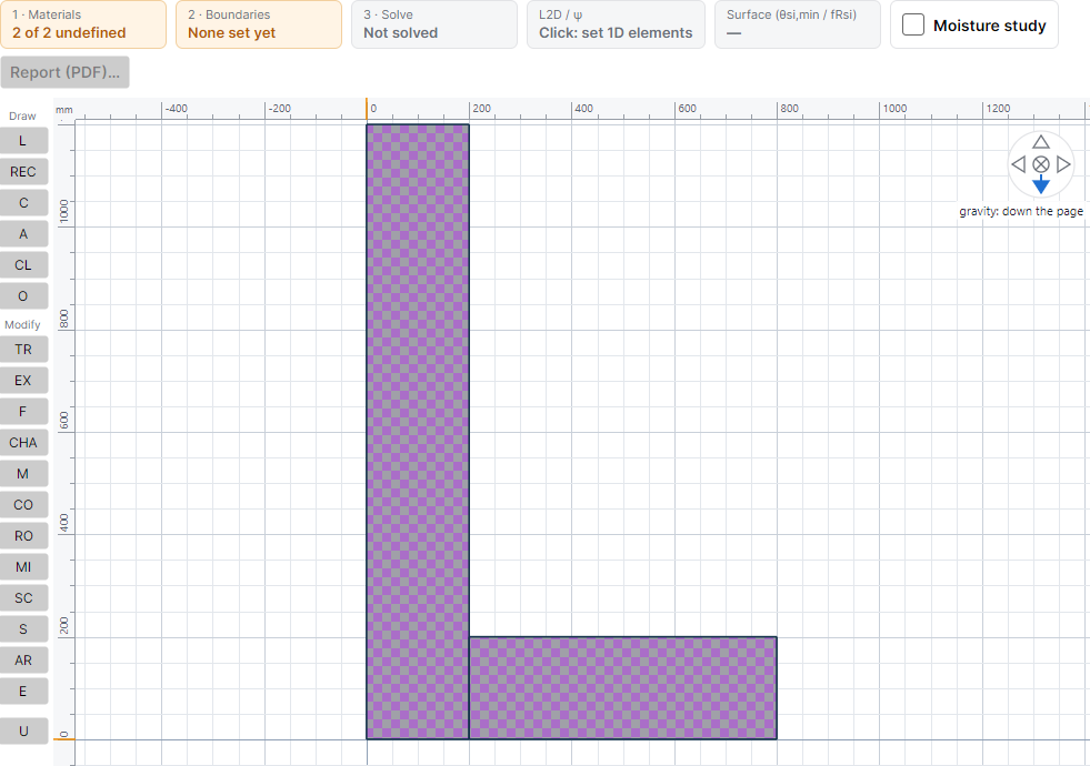
- A region with no material yet shows a purple and grey checker. Pick a material and click regions with the Paint bucket. Delete selected leaves a region out of the section; Restore selected brings it back.
The drawing tools work like AutoCAD®: type a command or click its button, then click points or type them (x,y, @dx,dy, @length<angle, or a length towards the cursor). Everything is in millimetres.
- Draw:
Lline,RECrectangle,Ccircle,Aarc,CLconstruction line (type an angle or a pitch such as 1:4; it turns towards your pointer's side),Ooffset. - Edit:
TRtrim,EXextend,Ffillet,CHAchamfer,Mmove,COcopy,ROrotate,MImirror,SCscale,Sstretch,ARarray,Eerase. - Selecting: click a line or region, or drag a box. Left to right (green) takes what is wholly inside; right to left (blue) takes whatever it touches.
- Snaps (F3): endpoint, intersection, centre, midpoint, perpendicular, nearest. Ortho (F8). Grid snap (F9). The crosshair shows while you draw and turns green when it snaps (View → Crosshair: always / only while drawing).
- Keys go to the command line: type a command and press Enter. Delete or E erases what's selected.
- Copy and paste (Ctrl+C / Ctrl+V): pick a reference point when copying, then the new point when pasting.
- Undo and redo (Ctrl+Z, Ctrl+Y) cover every change: lines, points moved, paint, boundaries, membranes, the ground model and 1D lines.
- Membranes go on the joints between materials, as lines: pick one (polyethylene, wall wraps, smart retarders whose sd changes with humidity, and Bradford, Rothoblaas and pro clima products), select the joints, Set.
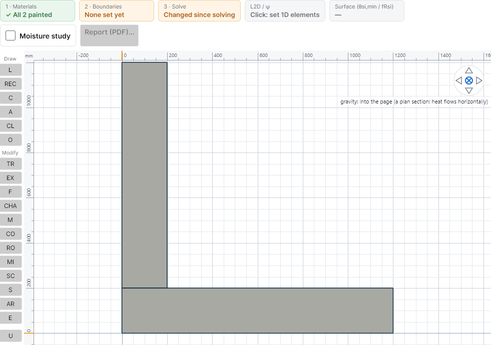
- Draw → Ground model builds the ground block for a slab edge from B′ and the wall. The gravity disc (top right of the drawing) says which way is down: click an arrow, or ⊗ for into the page (also Draw → Gravity). The report shows the same badge on its section pictures.
- Window frames: the materials include the PHI calibration panel (λ 0.035), which stands in for the glazing when calculating a frame.
Importing a PDF or a picture
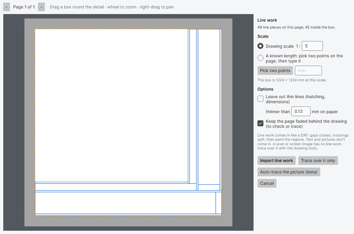
File → Import PDF or picture… Pick the page, drag a box round the detail, then set the scale: the drawing's 1 : n, or pick two points on the page (they snap to line ends) and type the real length between them. Three ways in:
- Import line work: for a PDF exported from CAD. Its lines and curves come in as geometry, exactly like a DXF. Tick Leave out thin lines to drop hatching and dimensions by stroke weight.
- Trace over it only: for a scan or screen image (a picture has no line work). The page sits faded behind the drawing, at scale, its bottom-left corner at 0,0; draw over it with
LandREC. View → PDF underlay shows or hides it; it is saved with the drawing. - Auto-trace the picture (beta): the picture's dark lines inside the box become straight lines. Text and 45° hatching are left out, near-square lines are squared and broken pieces joined. Clean line drawings trace well; hatched or sloping parts can come in pieces. Check every line against the faded picture and finish with the drawing tools.
PNG and JPEG screenshots open the same way (one pixel = one point: use pick two points for the scale).
How to draw a thermal bridge (and what to check)
Most of the set-up is done for you. These are the things that are easy to get wrong, and each one means drawing it twice. After every Solve, the model checks list anything that looks off, with the fix.
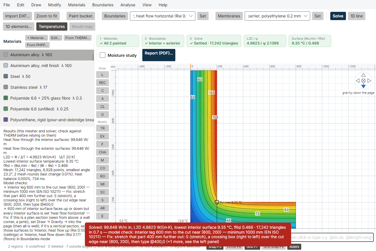
- Which way is down. A vertical section (eave, sill, slab edge) has gravity down the page; a plan section seen from above (wall corner, window jamb) has gravity into the page. Set it on the gravity disc, top right of the drawing, before anything else. It decides the heat-flow direction in air cavities and which interior surface resistance each surface should have. Check: "faces up or down but every interior surface is set horizontal" is usually a plan section left with gravity down the page.
- Draw far enough out. Each flanking part needs at least 1000 mm of interior surface from the junction to where the section is cut. Check: "Interior leg … mm, minimum 1000 mm", with the exact stretch to type (
S, a crossing box over the cut edge, then the@dx,dyit gives). Legs that run out to glazing are left alone: window models cut the glass short on purpose. - Cut edges stay adiabatic. Where the drawing is cut through a wall, roof or floor, leave the edge with no condition. Only real surfaces get Interior or Exterior.
- The right interior surface for the way it faces. Walls: heat flow horizontal (Rsi 0.13). Ceilings and the underside of roofs: heat flow up (0.10). Floors: heat flow down (0.17). Window frame edges and reveals: 0.20. Don't set 0.25 yourself: the fRsi (mould) run uses it automatically. Check: a surface whose direction doesn't match its condition is listed with the condition it should have.
- Every region painted. A purple/grey checker means no material yet; step 1 in the summary bar counts them. Take λ from the product's declared value where you have it (+ Material), not the nearest generic.
- Air: cavity or layer. Enclosed air in frames and framing: Air cavity (its λ comes from its size and the gravity). Air layers in a PHPP build-up: Air layer (PHPP). A cavity behind cladding open to the outside air: Air cavity, ventilated (to outside). For moisture it exchanges air with the outdoors; for heat it is still treated as a closed cavity in this version, so check how your method treats layers outside a ventilated cavity.
- Ground. Use Draw → Ground model (B′, the wall and the top outer corner) rather than drawing soil by hand. Checks: the ground block's size against the rules, and soil λ against 2.0 W/(m·K) (sand/gravel) unless the site's soil is known.
- 1D elements for ψ. Draw a 1D line through each flanking build-up (1D line) and measure its length from the outside (external dimensions, the default; only a slab edge is internal). The report says which way ψ was measured. The 1D U-values come from the PHPP where it has them.
- Before you trust it. The solve says settled, the heat balance is close to 0 %, the model checks are clear, and the 1D U-values match the PHPP (the report says matches or differs, never pass or fail). Then a competent professional confirms the result.
Boundaries, solving and results
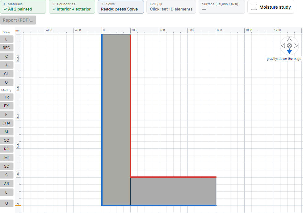
Turn on Boundaries, click the outside faces (Shift+click selects the run of faces up to the next selected one, or drag a box), pick the condition and Set. Each condition has its own colour.
- Interior: 20 °C, Rsi 0.13 (heat flow horizontal), 0.10 (up) or 0.17 (down).
- Interior, window frame edge or corner: Rsi 0.20 (EN ISO 10077-2).
- Interior, mould check: Rsi 0.25.
- Exterior: 0 °C, Rse 0.04.
- Adiabatic: no heat crosses (the cut edges of the model).
Air cavities follow EN ISO 10077-2; PHPP still air layers follow EN ISO 6946.
Solve meshes every region into triangles, solves steady heat conduction, then refines until no surface's heat flow changes by more than 0.5 %. The results are the heat flow through each surface, L2D = Φ / (θi − θe), the lowest interior surface temperature and fRsi = (θsi,min − θe) / (θi − θe). How it's calculated shows the full working with this model's own numbers.
1D elements in a drawing
ψ = L2D − Σ U·l: each flanking wall, roof or floor taken off is a 1D element, drawn as a dimension line on the detail.
- Click 1D line (or type
1D). Click where the element starts at the cut edge, then where it ends at the junction: on the inside face for ψ internal, the usual case. - Pick what it is:
- PHPP assembly: U from the PHPP, refreshed whenever the PHPP changes. The PHPP's U always takes precedence.
- My library: U from your 1D library.
- From this drawing: the layers straight through beside the line, U = 1 / (Rsi + Σ d/λ + Rse), read again on each solve. For even layers.
- Draw it…: a small drawing of the element on its own (e.g. one stud bay with adiabatic sides), solved: U = heat flow in ÷ (ΔT × interior face length). For framing, or anything not in even layers.
- Custom: the name and U you type.
The line floats off the detail like a dimension line, labelled "1D name (length mm)", and shows the same way in the report. 1D elements… lists them all to change, measure again or remove.
Moisture check (mould index)
The moisture check simulates heat and moisture hour by hour and reports the highest mould index (VTT model, ASHRAE 160 / AIRAH DA07 set-up). It is a transient heat-and-moisture (HAMT) model, not the Glaser method. Most junctions don't need one, so it is off until you tick Moisture study in the drawing's summary bar; off, it stays out of the report. There are four runs, from seconds to hours, all in the background while you keep working:
- Surface check, seconds: interior surfaces only. One heat solve at Rsi 0.25 gives each surface point its temperature factor; its hourly temperature and RH follow from the weather and indoor air.
- 1D build-ups, a minute or two each for 10 years: each 1D element's build-up on its own (a PHPP assembly, or one read off the drawing), as most hygrothermal tools run a wall. Several run at once.
- Quick 2D, minutes: the whole junction, one year on a coarser mesh. Screening, with the full run's time estimated.
- Full 2D: the whole junction, every year set, full mesh. What the report rests on. By default it takes 6-hour steps, dropping to 1-hour steps whenever the outdoor air is humid or a timber point is close to growing mould, so short wet spells aren't averaged away; the time estimate counts those steps from the actual weather. Tested against 1-hour steps: a timber-clad wall (1D) in Perth, Melbourne and Launceston within 3 %, and a timber eave (2D) in Perth over 4 years within 0.1 %. The 1-hour step is there for a final check.
Run (surface + 1D + quick 2D) in a drawing's Moisture window does the first three in a row. Start the full run from the same window, or with Run all full runs on the project page. Reports don't wait: until a detail's full run is done, its report shows the surface check and the quick run as screening, and says so.
1D and 2D side by side. The report sets each build-up's 1D result beside the junction's 2D result. The difference is what the junction itself adds, the way ψ is for heat.
Weather. Weather files can't be bundled with the app, so choose one per project:
- Download (NASA POWER, anywhere)… fetches a year for the site's coordinates, cited in the report.
- climate.onebuilding.org typical years: choose the downloaded zip as it is.
- From my weather files… uses a folder of your own, such as CSIRO's Australian TMY set (free from the CSIRO Data Shop).
- The PHPP's climate (only when a PHPP is open): its monthly climate rebuilt into hours, as a quick screen with no download. The result says which band the climate falls in, from its mean humidity: damp (73 % RH or more; in our tests the screen tracked hourly weather within −4 to +19 %), near the mould threshold (65–73 %; about −25 to +36 %, so run the site's hourly file before relying on it), or dry (under 65 %; it can miss rare wet spells altogether). Where timber is in the build-up, it suggests a membrane approach: a vapour-open water barrier on the cold side and a humidity-variable airtight layer, not polyethylene, on the warm side.
Files without rain (e.g. NatHERS TMY) still run, but give no driving rain, and the report says so.
Settings: bedrooms, indoor conditions (DA07, the PHPP's comfort band, or your own band for an under-heated house), wall orientation (default: the one with the most driving rain), exposure, rain deposition, height and starting moisture: new construction (2 × or 1 × the moisture at 80 % RH) or existing, dry materials for a renovation (a settling year in the site's climate is run first and not counted). Also the mould sensitivity of each material (untreated timber very sensitive, plasterboard sensitive, other materials medium resistant by default), and membranes and joints in each build-up.
Ventilated cavities. A cavity painted Air cavity, ventilated (to outside), or a build-up's ventilated cavity joint, exchanges air with the outdoors hour by hour. The rate comes from the weather file's wind on that façade, stack effect, the vents (10 mm slots top and bottom by default) and the cavity's own friction, which is why a deeper cavity moves more air. As a guide, 20 air changes an hour is about 1.5 cm/s of air rising up a storey-high cavity. With no wind in the weather (the PHPP's climate) a fixed rate is used. Analyse → Suggest a cavity… tries one behind the cladding on each façade (N, E, S, W) at 20, 25, 35 and 45 mm and gives the smallest that keeps the timber at or below 3 (and at or below 1). The cladding's own weather face is reported separately: its coating, not a cavity, decides that face.
Reading the result. Every result shows where it sits on the scale with a black dot:

- 1 or under, green: no growth, or the first microscopic traces.
- 1 to 2, yellow: microscopic growth.
- 2 to 3, orange: microscopic colonies; visible mould starts at 3.
- Above 3, red: visible mould expected. The NCC route (AIRAH DA07, ASHRAE 160) sets 3 as its limit.
When timber reaches 3, the result suggests a ventilated cavity to try.
The model passes the EN 15026:2023 Annex B benchmark (48 of 48 checks in 1D and 2D, at 1-hour steps, against the reference values as published by Better Building). Material data and indoor conditions are the biggest sources of uncertainty: check them for each job.
THERM packages
A drawing can go through THERM 7.8 and come back with THERM's own results beside BPA Junction's, a useful check while the Junction solver's validation is in progress.
- File → THERM package (ZIP)… saves the drawing as THERM's XML format, with BPA Junction's own drawing alongside. Paint every region first: THERM needs a material in each.
- File → Process a THERM package… (Windows, with THERM 7.8 installed) solves every detail in THERM in the background and writes a -solved ZIP beside it.
- Project → Solve all drawings in THERM (Windows, with THERM 7.8 installed; the item only shows there) runs every drawing in the open project through THERM and saves THERM's results into the project file itself: each drawing then shows THERM's heat flow and coldest interior surface beside BPA Junction's, on any computer, including a Mac. Edit a drawing afterwards and it says THERM's result is out of date.
- File → Open THERM results (ZIP)… shows, for each detail, the heat flow and coldest interior surface from THERM and from BPA Junction, and THERM's value for each air cavity.
- File → Email THERM package to BPA… (handy on a Mac, where THERM doesn't run) saves the ZIP and opens an email to Building Physics Australia; attach the ZIP from the folder window that opens. Your package is solved and sent straight back, and nothing is kept.
A detail THERM can't take, such as a region that wholly surrounds another and couldn't be cut open automatically, comes back marked with the reason; the rest of the package still goes through.
Exports, limits and verification
Export for THERM… writes a DXF R12 with one closed polygon per region for THERM's auto-convert. A THERM package (above) is the more complete route: materials and boundary conditions travel with the geometry.
Catalogue copy: ticking the catalogue box when generating a report also writes an anonymised copy (no client, address or names). Publish to catalogue… sends it for review; nothing appears on details.buildingphysics.au until it has been reviewed and approved.
How it has been checked:
- Layered wall against the hand calculation: exact (3.657434 W/m both ways); U read off the drawing and U from a drawn element both equal the hand value.
- The Junction solver against THERM 7.8 on the identical model (69 sample details sent to THERM as THERM packages): heat flow within a median 0.42 % (0.09 % on details without air cavities, where only the solvers differ), 48 within 1 % and 65 within 3 %; the coldest interior surface within a median 0.02 K. The remaining differences come mostly from how air cavities are valued.
- Moisture model, EN 15026:2023 Annex B benchmark: 48 of 48 checks, 1D and 2D, at 1-hour steps.
In progress: validation against EN ISO 10211 (its reference cases) and EN ISO 10077-2 (its frame examples), which Passivhaus certification needs. Until it is done, reports from the Junction solver say so: for certification, confirm the result in a validated tool such as THERM.
Known limits:
- Models with a soil block (slab edges, sills on slabs) can differ from THERM by up to about 9 % on the ground heat flow; this is being investigated.
- Air cavities: BPA Junction's own cavity method can differ from THERM's by a few per cent on details with cavities (above).
- Ventilated cavities count as closed cavities in the heat calculation (ψ) for now.
- Not modelled yet: ISO 15099 / NFRC cavity radiation, glazing systems from WINDOW, three-dimensional effects.
- A 1D moisture run takes a build-up on its own; the 2D run is what sees the junction.
- Auto-trace is a beta: check every traced line.
Check every result before relying on it.
Coming later
- Validation against EN ISO 10211 and EN ISO 10077-2.
- Screenshot tutorials for the drawing guide.
- A material choice for PHPP layers whose names aren't recognised.
- Air-conditioned indoor humidity, exposed claddings (sun, night sky), a second orientation.
- Material suggestions from DXF hatches.
- A designPH plugin export.
Not planned: DWG import (DXF and PDF are enough), the Glaser method, and pass/fail wording: the report states values, and a competent professional judges them.
Trademarks
AutoCAD is a registered trademark of Autodesk, Inc. Windows is a registered trademark of Microsoft Corporation. macOS is a registered trademark of Apple Inc. PHPP (the Passive House Planning Package) is a product of the Passive House Institute. THERM and WINDOW are software from Lawrence Berkeley National Laboratory. Bradford, Rothoblaas and pro clima are the trademarks of their owners. Building Physics Australia is not affiliated with or endorsed by any of them; the names are used only to say what BPA Junction works with.